

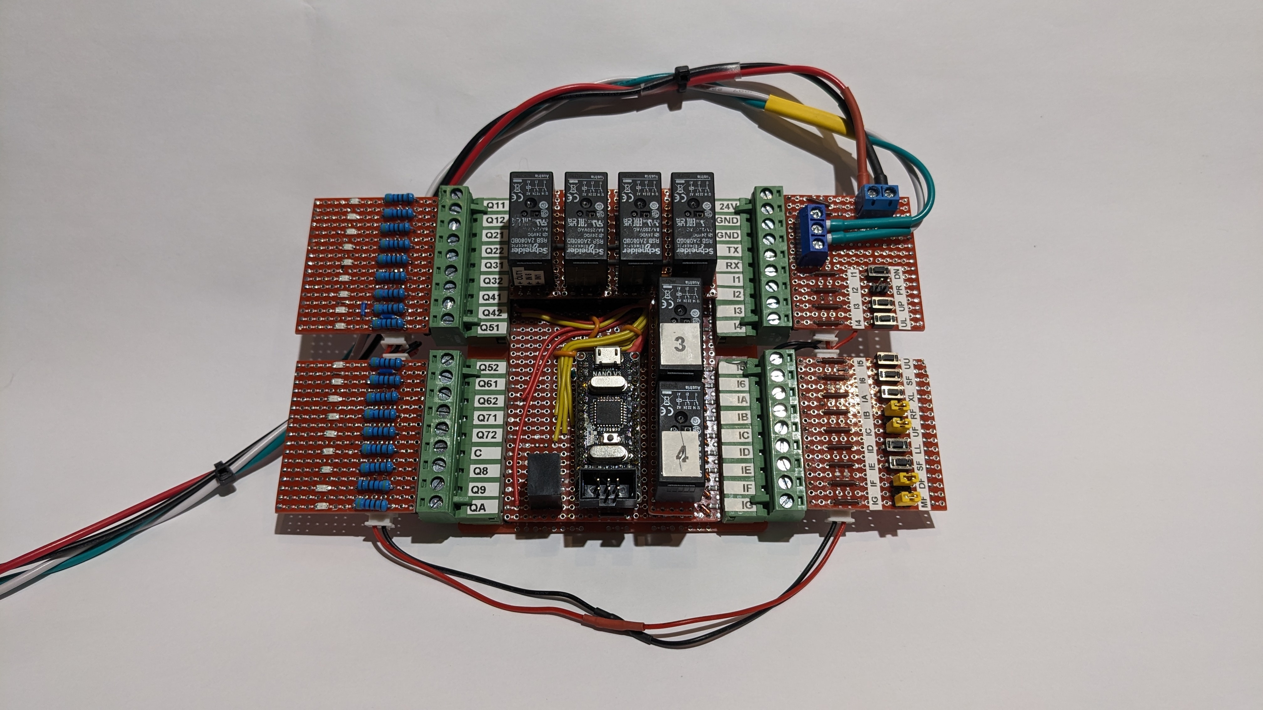
This is the replacement controller I built for the wheelchair lift. The controller itself is in the middle. The four board on the left and right are a testing harness. The red and black wires are 24VDC and the green and white ones TX and GND for monitoring with a terminal program on my notebook (puTTY).
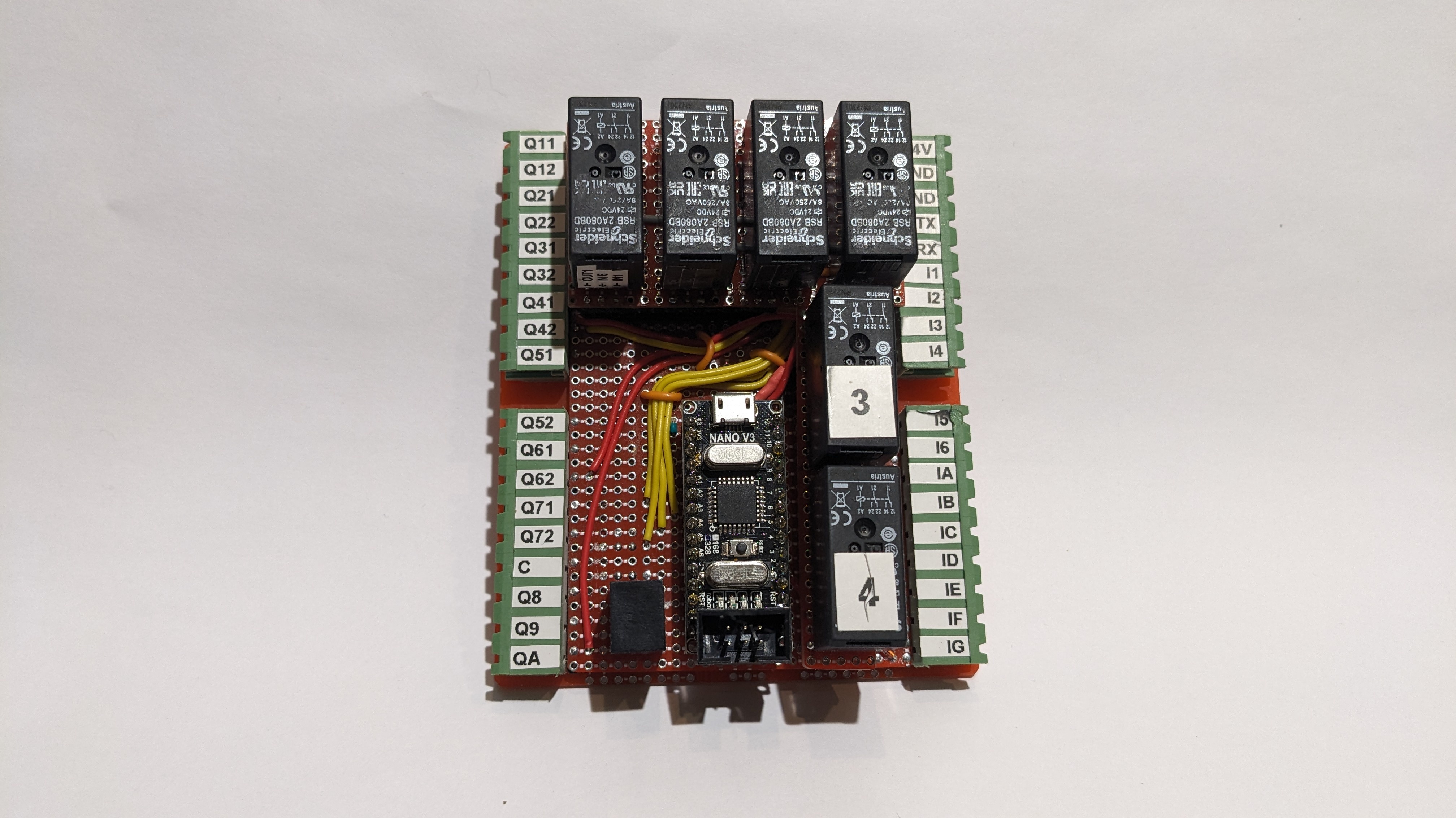
Without the test harness it looks like this.
I was trying to squeeze a LOT into the BID box that I’m using for this project. I had to stack boards to get everything in.
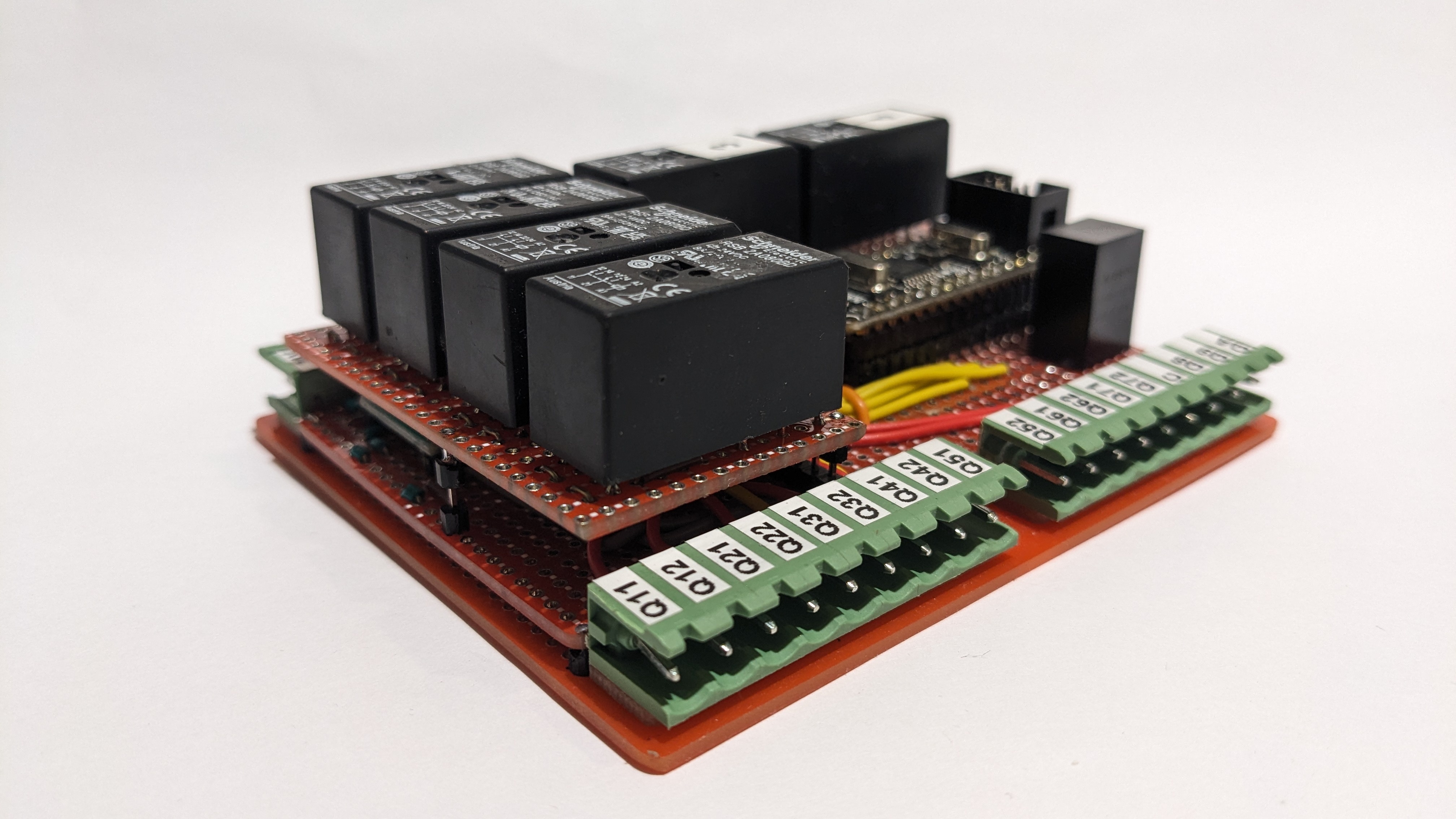
The bottom most board is a standard bottom board for the BUD case. It has holes along each side for 2.54 screw terminals and pluggable screw terminals. I’m only using that board to mechanically connect the project to the BID case and for the screw terminals. I almost always use pluggable screw terminals because they’re awesome. I can unplug four plugs instead of unscrewing 36 screw terminals and trying to keep the wires straight.
There are two top boards. The one on the left carries four relays which turn the negative logic of the Darlingtons into positive logic for the lift. They send 24VDC out to the contactors that run the motors and the door lock. The other small board at the rear has two safety relays which switch power coming in through a bunch of safety switches out to the battery relay and the main contactor.
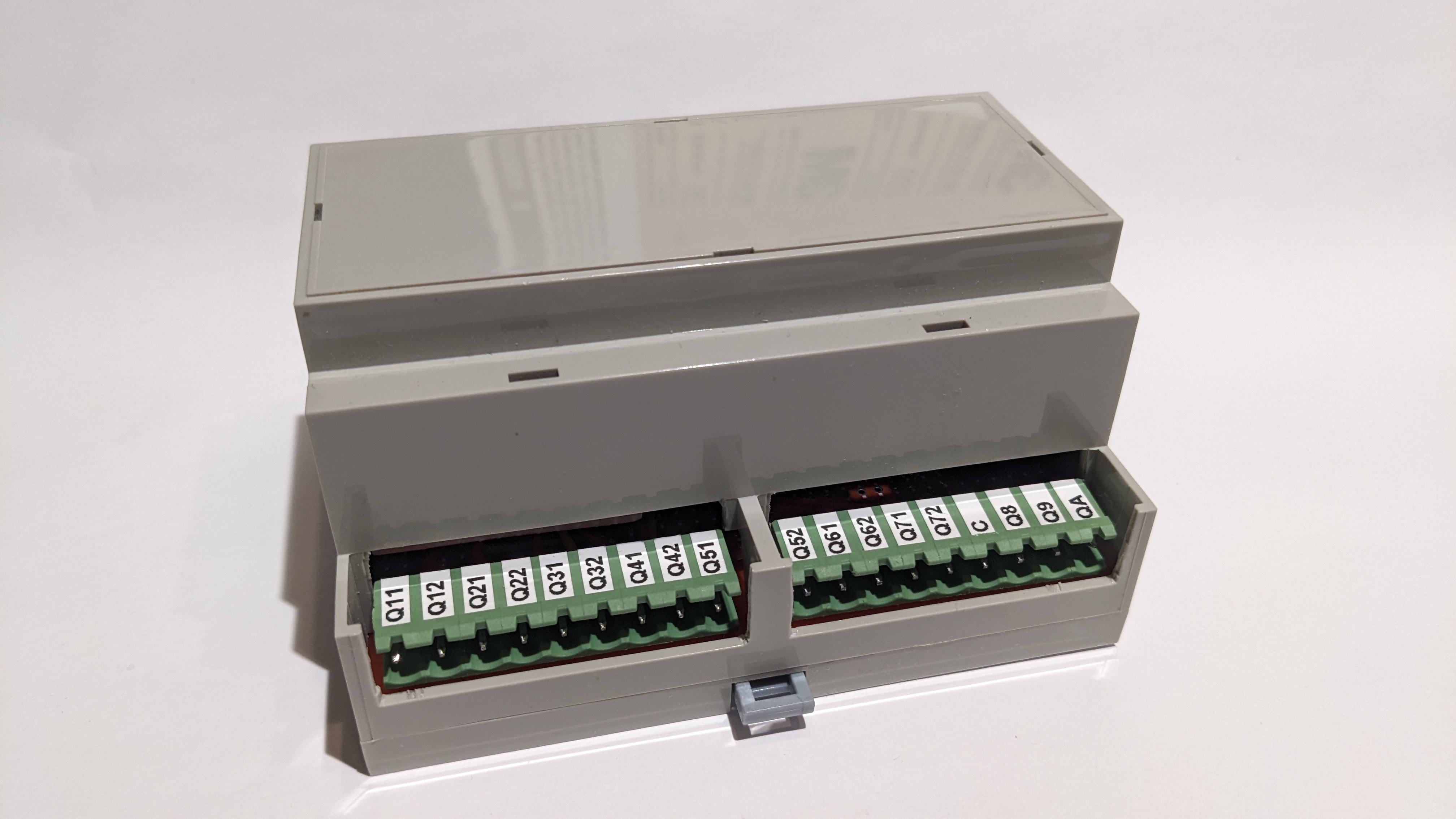
This is what it looks like assembled into its BUD case.
This is all built around an Arduino Nano with a program that I wrote in Great Cow BASIC.