Sorry if this isn’t the right community. I’m adding blinkers to a side-by-side and I have the blinkers working. However I can’t understand how to connect the hazard switch to the blinkers without losing the blinker functionality. When I connect them it makes both blinkers go off when I try to use the blinkers. Is someone able to point me in the right direction? Thanks!
This (fairly simple) diagram shows one way.
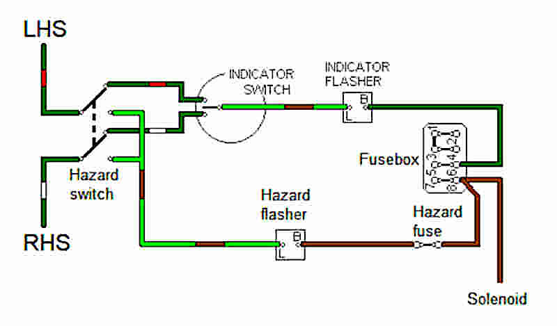
http://www.mgb-stuff.org.uk/images/haz3.jpg
You have the hazard switch which, when engaged, connects both L and R to the flasher circuit and disconnects the indicator switch. The turn indicator switch is either off or it connects left or right to the flasher circuit (via the hazard switch).
The page that this is from has some additional ways to do it.
http://www.mgb-stuff.org.uk/s_hazard.htm
If you are still struggling, let us know how the blinkers are wired and share a wiring diagram if possible?
If you ignore the hazard switch in the image I posted that is what I have wired. 1 & 3 on the blinker switch are connected to blinkers on each side. I got lost when the hazard came into play… Do you understand what the directions are saying with “+ switch negative”, “negative led light inside switch”, etc? I looked at the diagrams you linked but it’s hurting my brain even more at this point :)
Yeah that diagram is just a bit tough to follow. (And by that I mean …wtf is that unholy mess lol). I can see why you’re struggling.
I gather the switch is illuminated by an LED so there are two pins to power that internal LED. For now just ignore those. You can hook em up later.
I am not sure what they mean by “+ switch negative” and “+ switch positive”. Is this by any chance translated from the original Chinese ? :)
If you have a multimeter it might be helpful to just figure out what the switches are doing.
I gotta think about this some more because this diagram makes no sense right now.
Ok sorry for this janky drawing but I think this is a correct representation of how to wire everything. Maybe?
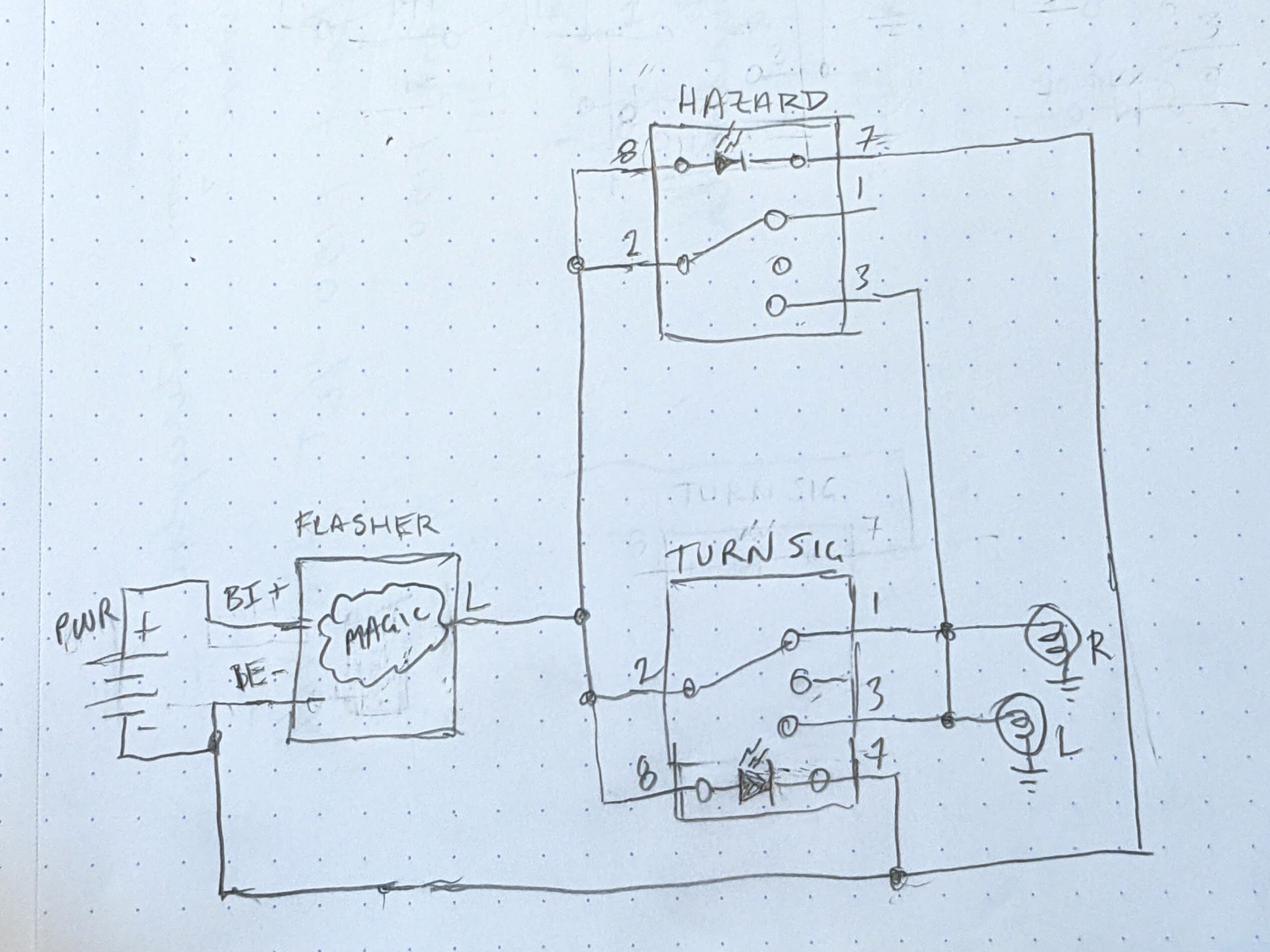
What should happen is with hazards on, both L and R lights blink together and the turn signal switch has no effect. When hazards are off, the appropriate turn signal operates if you select R or L turn otherwise nothing flashes.
Thanks! I think that is what I was originally trying. By adding the hazard “3” connection to both sides of the blinkers it ends up connecting them so that whether I use blinkers or hazards it’s all the same. I’m going to do some more debugging with a multimeter and see if I can understand the switch more. I’ll probably just end up getting diodes and wiring it like this diagram with diodes. Just bothering me that I might be missing something.
Gotcha. I think diodes are the easiest solution here. Idk what they were thinking with these instructions.
If the hazard switch was a dual pole, then you could connect the right side to one pole and the left side to the other pole and then it would only connect Left and Right when hazards are on.
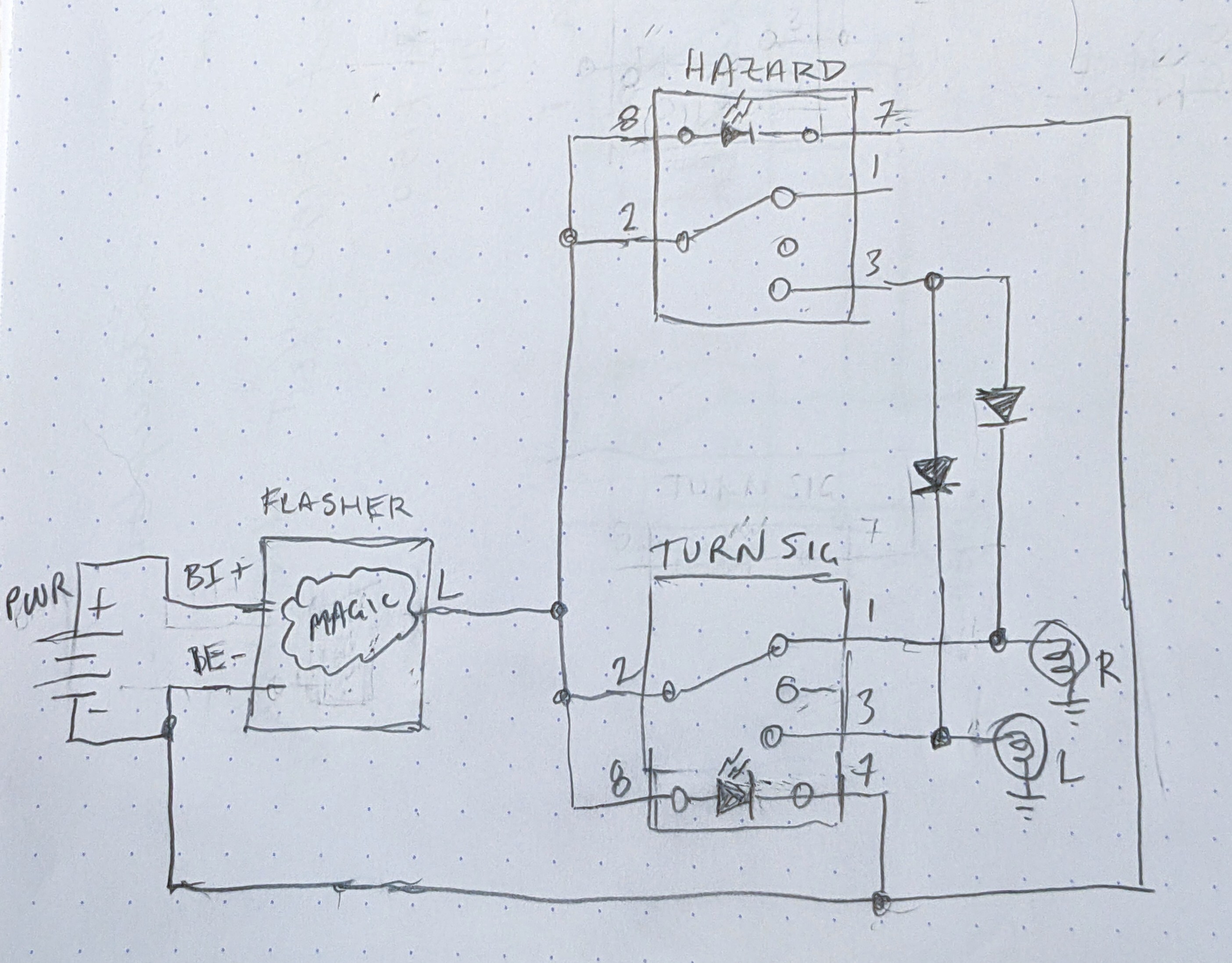
With diodes:
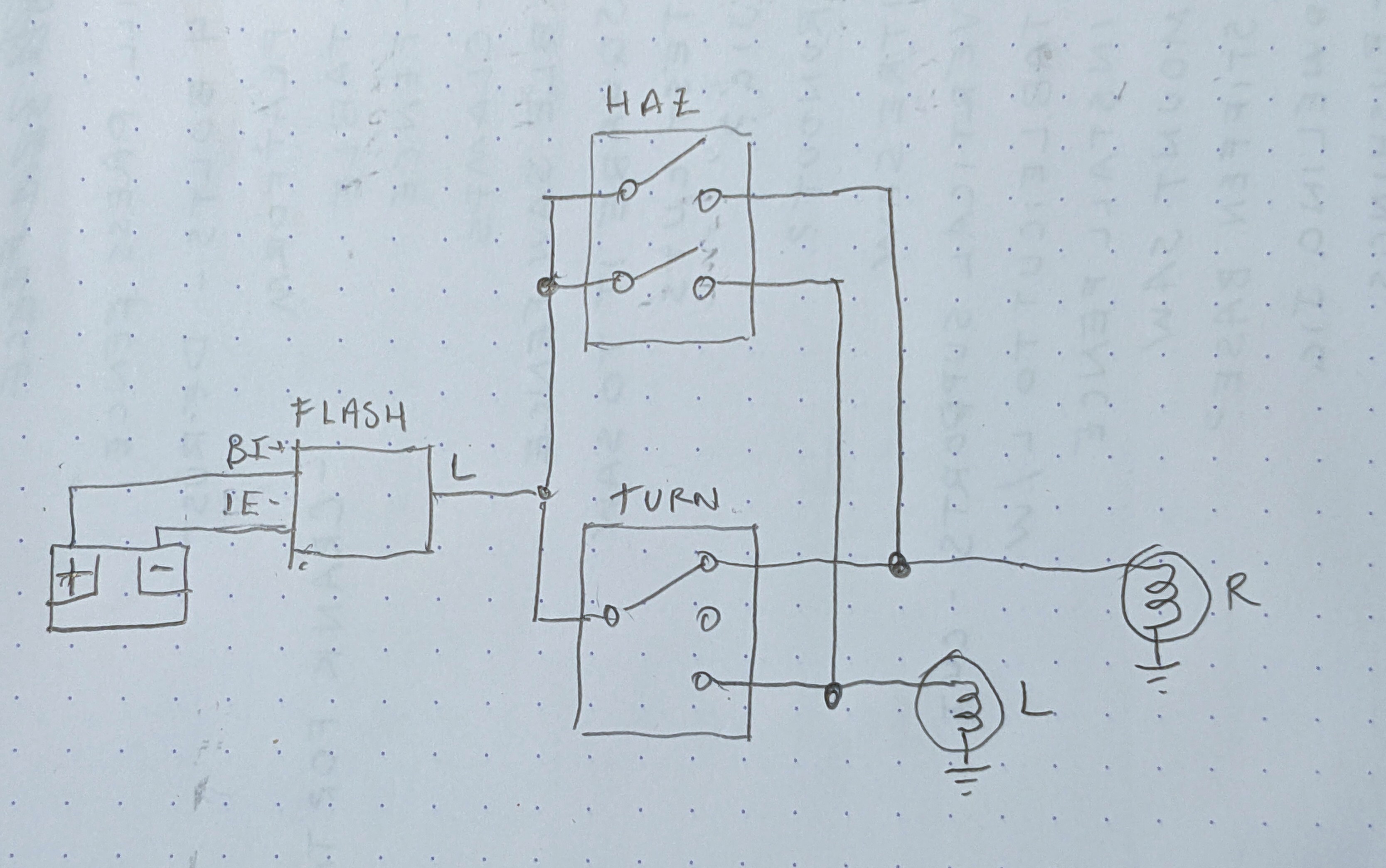
With dual pole hazard switch:
Added the diodes today and it’s all working great! Thanks for helping me understand this!
That’s awesome, congrats!
I’m no expert, just a hobiest with a basic understanding of electricity.
If I understand correctly, you basically bridged the turn signal bulbs together when you wired in the hazard relay.
I would install 2 diodes (12v 10amp or so) between the hazard relay and the turn signal bulbs. Diodes only allow electricity to flow one way, so it should prevent current from flowing from one bulb to the other through your wiring
Yeah that’s the only thing I can think of too. I don’t think the kit came with diodes which made me think I was misunderstanding something. Thanks! I will have to go with this unless there is another trick.
Edit: ended up going with diodes and it works great!
