
First of all, I apologize for the lack of a “formal” schematic… I tried to draw one out, but got buried in the nuances of it :)
Second, I’ve done enough research to have some idea of what my problem is: namely, I need a decoupling capacitor in the mix. Problem is, I’m new enough to this that I’m not 100% sure where to put it, nor what capacitance I should use.
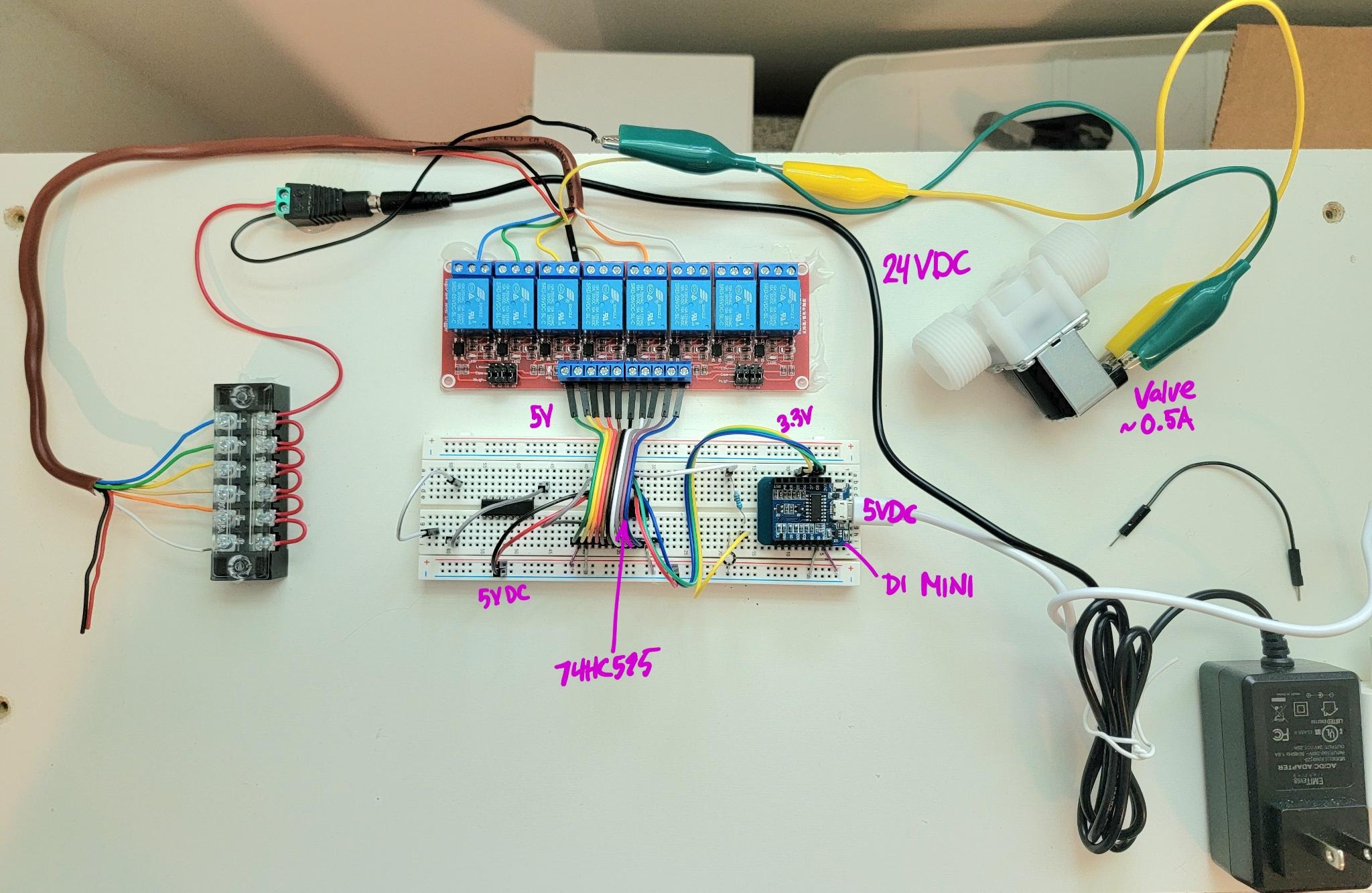
So the setup: -I’m using a Wemos(like) D1 Mini to drive 8 relays via an HC595 shift register -The D1 Mini microcontroller, HC595, and relay module are all powered by the same 5V DC and ground -The microcontroller addresses the shift register via 3.3VDC data pins -The relays power a water valve via a separate 24VDC power supply and transformer - plugged into the same AC outlet
And the problem: everything works just fine UNTIL I actually add the 24VDC power load. Once that’s done, the results are very erratic… usually turning on the correct valve correctly, but rarely turning it off in the same way. As I mentioned, I intuitively suspect noise in the data caused by the sudden power to the valve… but it doesn’t make too much sense since everything is on different power supplies.
Any guesses as to where I need to put some capacitor(s)? Thanks!!
Not entirely sure, but maybe these help you somehow:
The relay has a coil which requires 0.35W. The chip seems to have a maximum output current of 35mA.
The ‚switch on current‘ of an inductive load is usually 3 to 5 times higher than the ‚hold‘ current.
The valve may not have a free-wheeling-diode. This could create an issue by creating strange voltage spikes on all your supply voltages (connected by GND).
Yeah, decoupling cap here might as well just help OP fry the chip more effectively by ensuring it can sink all that current.
Solution here is probably a transistor/MOSFET that the chip turns on, which in turn turns on the relay. Relay coils are inductors, so that probably also needs a diode to protect the transistor from inrush current and also the kickback when it turns off: inductors resist changes, so it’ll try to keep sinking the current and result in temporary spike of very high voltage: https://spinningnumbers.org/a/inductor-kickback.html
Thanks so much! It turns out that the relay (8x) module I’m using - https://www.amazon.com/gp/product/B00LX3UH9C - has isolated relays… but I’ll try a diode, too.