
If I were to take a standard AC to DC converter, say a laptop charger, and hook up the input side (which expects 120VAC at 60Hz) to a DC power supply of some sorts, will the electricity still be “converted,” or will it just not work at all? I am clearly very uneducated when it comes to electronics (albeit working on it) so I would very much an ELI5 answer Thanks!
It will not work… if you look at a simple AC to DC converter (half-wave rectifier) either output = 0 volts or output = input - conduction losses, depending on how you polarized the DC source.
In another circuit (full wave rectifier), the diodes will be polarized such at two will allow current flow. output = input - conduction losses
If the rectifier is something more complex (12 pulse rectifier)… this circuit relies on transformers. If you put DC on the primary of the transformer then the output will be 0 volts and thus the rectifier output will also be 0 volts. In this example I’ve ignored the fact that the transformers have 3 terminals and the DC source would only have 2.
I’m less knowledgeable of more elegant rectification methods (such as active rectification)…
Interestingly… the fundamental DC to AC converter (inverter) is the same circuit as the full wave rectifier, with the diodes replaced with controllable switches (SCRs, IGBTs, IGCTs, MOSFETs, ect.)
In most cases it will work fine as the first thing a good power supply does to the incoming electricity is converting the AC to DC using a full bridge rectifier. If you already supply DC, the current will just flow through it without a problem and the power supply simply continues to do its stuff.
However note that the DC input voltage needs to be relatively high. About sqrt(2)~=1.4 times as high as the rated AC voltage should be fine. So if you have a power adapter that’s rated for 120 to 240 VAC, you should give it something between 170 and 340 VDC. This is obviously very high (and dangerous). Plugging in a normal car battery or the output of a usb charger or something like that will likely do nothing.
The way you get dc from ac is by using a full bridge rectifier that changes the negative peaks of ac into positive ones. If you where to put dc through it it should just pass like normal
Unless there is a transformer. Also, it may just catch fire depending on the input voltage
can someone explain this imagine?
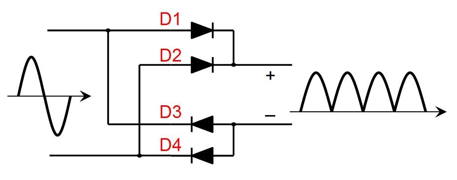
Think about the circuit over time. The sine wave on the left is the input.
When the sine wave is positive, the top wire is positive and the bottom wire is negative. That means d1 and d3 are both positive and d2 and d4 are both negative.
Diodes “forward bias”, meaning they allow electricity to flow, when you have a positive on the triangle side. This also implies a negative on the straight bar side. If the positive is on the straight bar side, then it won’t conduct. You have to have a negative on the straight bar side.
Note: Keep in mind positive and negative means in relation to each value. So if one side is 5 volts, and the other is 0, then the other side is negative compared to the positive side.
So with that in mind, when the sine wave is positive, greater than 1,then d1 and d4 are conducting (there an implied loop on the left side).
When the sine wave is negative, then d2 and d3 are conducting. Because these two diodes are flipped, the high value goes to the top wire on the output which is now seen as a positive. The input is different, but because you’ve flipped the wires, the output is still the same. Now all current flows in one direction no matter the input. AC is now DC.
Shorter verison: positive side of the sine wave makes d1 and d4 conduct. Negative side makes d2 and d3 conduct. Since d2 and d3 cross over, they effectively turn the negative into a positive value.
Thank you for your response! Here’s my understanding so maybe you can point out where I’m getting confused.
When the AC is positive, there is current coming in from the top line. The current goes to D1 & D3. Since it’s positive, it gets through D1 and creates a positive on the DC side. Since it’s hitting the line part of D3, it isn’t allowed through and it stops right there.
When the AC is negative, there is current coming in from the bottom line. The current goes to D2 & D4. The D2 allows the current to go through on the positive side, and continues to provide a positive current for DC. When it gets to D4, it is hitting the line side of the diode, so it isn’t allowed through.
Both D1 & D2 allow for a positive charge, while D3 & D4 prevent a negative charge from coming. However, couldn’t that be achieve without havining D3 & D4. Since there is no negative charge on the DC side, D3 & D4 never allow current through at all. If we just cut the wires to D3 & D4, wouldn’t it be the same outcome? What are their roles?
Kind of. You’re on the right track.
What you’re missing is that there is a loop. Imagine a resistor being connected to negative and positive of the load. Since it’s about relative voltages not absolutes, d1 and d3 both conduct. A positive on the triangle, or a negative on the bar will make them conduct. For electricity to flow you must have a loop from source to load and back to source. So current would flow from the source through d1 through the load through d3 and back to the source.
Hope that makes more sense.
You could remove d1/d4 OR d2/d3 and you’ll have a half wave rectifier, so you’ll get every other peak.
Ohhh!! I think get it now. D3 & D4 are necessary to complete the loop. Otherwise, there would be alternating current on the bottom phase going into the DC negative once per cycle, causing a short. So when D1 is allowing positive power through on the top of the phase, D4 is allowing negative current out to the source. When the AC is on the bottom phase, D2 lets positive current in, and D3 let’s the negative current out to the source. Is that correct?
Please excuse this attempt from a mere technician.
The waveform on the far left is the electrical signal fed into the rectifier. It illustrates a current that starts at zero, then reaches its full positive amplitude, then comes back to zero, then reaches the full negative, then back to zero. This represents an AC or alternating current. This is the way electricity comes out of your wall, usually.
DC or direct current is instead just a constant horizontal line. Ideally no change in the current. This is what we get from batteries and is used in most of our smaller devices like computers and smartphones. So naturally its handy to have a device that “adapts” the AC to DC. A common part of AC to DC Adapters is a rectifier.
The diagram in the center of the image is the schematic of a full bridge rectifier. It shows the two wires that feed into the rectifier on the left, these are then split into an arrangement of diodes represented by triangles with lines at their tips. Diodes essentially only allow current in one direction. The line is representative of a “direction” of the flow. The particular way these diodes are arranged means that no matter what kind of signal is fed in it will never produce a negative voltage at the output.
By using this arrangement we can feed in the AC signal and sort of flip the negative of part of that signal so the waveform looks like the one on the right. You can see that the waveform now is only above the line representing zero.
This is however only one step in the process of a power regulation and so as others have pointed out its not as simple as it may seem. Usually a transformer is used to step up or down voltages, and those are not designed to be used with DC and I believe could be damaged?
“DC or direct current is instead just a constant horizontal line.”
Your explanation is totally correct. (I replied as well just to break it down a little further for OP). I know I’m being a little pedantic, but DC does not have to be constant. DC can also pulse and change. The main difference is whether or not the signal remains positive. If it goes negative, then it is AC. The change in polarity is what matters, not how constant it is.
Ah yes, thanks!
Good explanation.
As @directive0 said, the diodes (triangles in the above circuit) only conduct in one direction.
On the AC wave (top left) in the positive half, two diodes are conducting. In the negative half, the other two diodes are conducting.
The two sets of diodes are connected so that the positive half and the negative half of the sine wave come out on the same line. Since the waveform on the right of the image is all positive (ignore the bumps), it is considered DC.
If I may, could I ask some more clarifying questions?
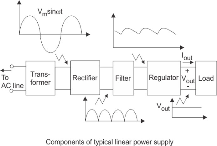
What does a transformer do? Does it lower the voltage of the power lines coming into the house?
So the rectifier converts the power from AC to DC?
What is the filter filtering out? It seems like maybe it makes the positive current stay powerful enough to maintain a minimum positive charge.
Does a regulator work by assessing the need of the device using power and then provide the power according to the needs?
Transformers raise or lower voltage of ac circuits. They also do the opposite to current, e.g. Raise voltage, lower current.
The rectifier makes all the voltage positive (or negative, but all the same). So yes, AC -> DC
The filter basically uses inductors and capacitors to act as storage. Using capacitor as an example, it’ll start charging when the wave starts to rise. once the wave goes down, the capacitor discharges which keeps the output more positive. You can see that in the image by full humps before and partial humps after. It’s still bumpy, but it never goes to zero.
The regulator can do a couple of things, mostly it’s used to ensure a constant output. In it’s most basic, it’ll be another diode that if voltage goes above a certain threshold, it shunts it away from the load. So if the output of the filter had a minimum of 5 volts and the regulator was set to 5, you’ll end up with a constant positive 5 volts because the diode is shunting away all the extra voltage.
Regulators can provide both over and under voltage protection in case there is fluctuations in the circuit.
Thank you!
It depends! Most AC to DC converters actually convert from AC to DC back to AC (at a higher frequency) then to DC again. The higher frequency means you can use a much smaller and lighter transformer for the same power. Depending on how it does the first AC to DC step, you could be ok giving it DC, but I wouldn’t do it unless the power supply says it’s rated for it.
It’s actually very hard to predict without looking at the PSU. And depending on the design, the failure will be by shorting your DC current supply, so I really don’t recommend testing it.
But many designs handle a DC supply perfectly fine.
Depends on how it works. I would expect that some would work but soon fail due to some components being overstressed, and others not to work at all.
I’m not an expert but as it is commonly explained, the first component of many (all?) switched mode power supplies (almost all laptop power bricks are SMPS) is a rectifier. If you feed a full bridge rectifier with DC, half of it will be unused while the other will carry all the current. The rest of the power supply after that should not care.
So in theory it should work, at least up to roughly half the rated load. But there may be other components like power factor correction circuits, safeties, or some details that those descriptions glossed over that make it not work.
Counterintuitively, if the device supports a wide voltage range (as many do) higher voltages may be better (as in less likely to fry it) as they require less current.
I think if a plug, or component, that’s expecting alternating current input, gets direct current input – it won’t work.
But I’m super dumb, so I’m really interested now in the answer to this question.
No, in that case you will need a DC to DC converter. They work differently.
That’s kinda what I was thinking. Will anything be ruined in this case? What prevents it from working?
I would think it’s because a “receiver” of AC current has to be specifically designed/set up to receive an alternating current. If it receives a direct current, it either doesn’t know what to do with it, or it explodes.
Again though: I’m dumb, so please take my
opinionthoughts with a grain of salt.