I don’t care what’s it gonna take. I just want a connection. I guess I can connect the VCC to another voltage source, but I have the same thing happened to TX on another circuit board, although that one can “flip” (it is still attached marginally… at one end).
Board: T Deck Lilygo.
Usually you can scrape off the solder mask to expose the copper layer, then use a bodge wire to connect the trace to the connector.
This is mostly likely the best solution. There are land repair kits but it does take a lot of finesse to get those right.
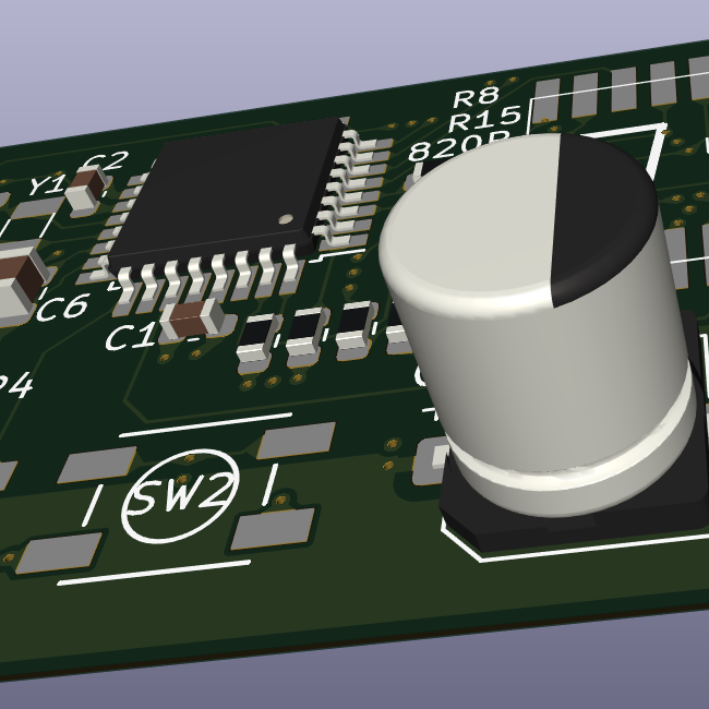
scraping off the solder mask and then soldering a wire to it also takes a lot of finesse. I have primitive equipment and and not that skilled. I probably end up butchering it. What about connecting bodge wires directly to the ESP? For the 3V as well as TX/RX (if they are broken too): https://www.dropbox.com/scl/fi/z16hluqgr6eca1w3kz3j3/TDeck-circuitboard.png?rlkey=lpdhqm5cq0crldp02jcz0agc6&dl=0
Looks like that goes to a via. Could scrape the solder resist back there and bodge straight in rather than try and hook up to the trace.
goes to a “via”? Meaning it’s not directly to the ESP? Is the schematic I provided not what it seems?
rather than try and hook up to the trace.
well I never said I’d hook it up to the trace, right? Or am I misunderstanding?
So, let me explain. The trace that breaks from the VCC of the P8 IC goes up and to and through a few holes. Those holes lead into the the board to get the needed 3V. You can also go bodge wire from the VCC leg of the P8 direct to the pin 2 of the ESP. You are reading the schematic correctly.
so if I understand correctly, I can either use a pin to solder a bodge wire onto, or solder a bodge wire directly onto the ESP? Hmm then I rather opt for the ESP since this has a larger area to solder onto than the pin.
Yes, bodge wire from the leg of the IC with the busted VCC pad to the 3V leg of the ESP as laid out in the document.
If you know where that chip goes, you could bodge straight to it as well. 3V should be fine. I would imagine tx Rx would be point to point as well. Someone correct me if I’m wrong.
Should be easy. When you follow the lost pads’ trace, it goes through a through-hole just above the RTX pad. Scratch it free, solder a small wire in there (verify that you’ve got contact!), then solder the connector onto the remaining pads and solder the wire to the VCC pin of the connector.
Pro tip: Don’t yank on the cables!
I yanked a connector that I wanted to remove. I don’t have needle thin nippers/pincers, and when I held my iron against the pads nothing happened. Am I missing something?
I guess a good set of nippers, but idk man…
I just fixed a similar problem while I was replacing an SMD cap. Same solution as the rest of the comments: Solder and a small wire. (It was just a larger decoupling cap anyways.)
Actually, I expanded on that in an extreme way with more solder and more wire to fix the joints on a barrel jack that was breaking off on the same board from above. My point is that brute force repairs are OK, even if it looks like shit. A simple repair can go a very long way, actually.

